Standard Stainless Sheet Sizes for CNC Cutting

Are you trying to optimize your CNC cutting jobs but find yourself losing profit to material waste? Selecting the wrong stainless steel sheet size for your project can lead to poor nesting, excessive scrap, and increased handling time, directly impacting your operational efficiency and bottom line.
Standard stainless steel sheet sizes for CNC cutting are typically available in imperial dimensions like 4'x8', 4'x10', and 5'x10', and metric equivalents such as 1219x2438mm, 1219x3048mm, and 1524x3048mm, providing predictable stock for global fabrication and manufacturing operations.
Choosing the right sheet is more than a matter of simple dimensions; it’s about creating a streamlined workflow from inventory to final part. The size of your raw material dictates nesting efficiency, cutting time, and even the wear on your CNC machine. As the Global Business Director for MFY, I’ve seen firsthand how a strategic approach to sheet sizing can transform a company's production economics, turning potential waste into tangible profit.
The true art of efficient CNC cutting lies in harmonizing the project's requirements with the available material formats. Simply defaulting to the largest sheet size isn't always the most cost-effective strategy, especially for smaller, intricate parts where a smaller sheet might yield less overall scrap. I recall a client in the engineering sector who was manufacturing complex machine guards. They were using large sheets and experiencing significant waste. By analyzing their part geometry, we recommended a less common but standard-sized sheet that allowed their nesting software to fit more parts per sheet, drastically improving their material yield. This is the consultative approach we champion at MFY—looking beyond the catalog to find a solution that fits your specific operational puzzle.
How to determine the appropriate stainless sheet size for your CNC project?
Facing a new CNC project and feeling uncertain about which stainless sheet size will deliver the best value? Choosing incorrectly can mean paying for steel that ends up in the scrap bin. This decision directly influences material yield, a critical factor for profitability.
To determine the appropriate stainless sheet size, analyze the geometry and quantity of the parts to be cut. Utilize nesting software to simulate layouts on various standard sheet sizes, selecting the one that maximizes material utilization and minimizes scrap for that specific job.
The process of selecting the right sheet size is a crucial first step that sets the stage for either efficiency or waste. It’s an exercise in foresight, balancing part dimensions against stock availability to maximize your material yield. The goal is to view each sheet not as a blank canvas, but as a finite resource to be optimized. At MFY, we often work with clients to make this determination. I recently guided a new equipment integrator in India through this process. They were bidding on a large contract for food processing conveyors, which required hundreds of unique side panels and brackets. Initially, they planned to use a single, large sheet size for simplicity. We sat down with their engineering team and ran a nesting simulation using two different standard sheet sizes from our inventory. The analysis revealed that using a combination of a larger size for the main panels and a smaller, narrower sheet for the brackets could increase their overall material yield by 18%. This simple change in procurement strategy made their bid significantly more competitive and ultimately helped them win the contract. It’s this kind of detailed, application-specific guidance that builds truly efficient supply chains.

Determining the optimal sheet size is a blend of art and science, a strategic decision that reverberates through your entire production workflow. It's about moving beyond the habit of ordering "the usual" and adopting a project-specific, data-driven approach. The most sophisticated CNC machine in the world cannot compensate for a poorly chosen raw material format; efficiency begins long before the laser ever fires. For my clients, whether they are mass-producing components or creating bespoke architectural pieces, mastering this initial step is fundamental to controlling costs and ensuring project success. The dialogue we foster at MFY is not just about fulfilling an order, but about co-creating a strategy for material consumption that delivers maximum value.
The Central Role of Part Geometry and Nesting
The most critical factor in sheet selection is the size and shape of the parts you intend to cut. The process of arranging these parts on a sheet to minimize waste is called nesting. Modern CAM (Computer-Aided Manufacturing) software is incredibly powerful, using complex algorithms to test thousands of layouts in seconds. Your first step should always be to import your part files into your nesting software. Create virtual layouts on several different standard sheet sizes that your supplier, like MFY, has readily available. The software will provide a clear, quantitative measure of material utilization (yield) for each option.
For projects with large, rectangular parts, a larger sheet (e.g., 5'x10' or 1524x3048mm) is often efficient, as the parts can be tightly arrayed with minimal gaps. However, for projects involving many small, irregular, or curved parts, the story changes. Sometimes, a smaller sheet (e.g., 4'x4' or 1219x1219mm) can be surprisingly more efficient. The software might find a more compact nest on a smaller surface, leaving less unusable scrap around the edges compared to spreading the same parts out on a much larger sheet. It’s a counter-intuitive concept that can only be revealed through simulation.
I worked with a client who manufactures custom signage. Their projects were a mix of large letters and small decorative elements. By nesting all components for a single job together, they found that a 4'x10' (1219x3048mm) sheet often provided a better yield than the wider 5'x10' sheet, because the narrower width allowed the software to tuck smaller pieces alongside the larger ones more effectively, reducing the total square footage of material required.
Balancing Job Volume Against Inventory Costs
The second consideration is the scale of your production run. For a one-off prototype or a very small batch of parts, the absolute highest material yield is less critical than speed and simplicity. In this case, using a common, in-stock sheet size that you already have on hand is likely the most practical choice, even if the nesting isn't perfect. The cost of ordering a single, special-sized sheet would outweigh any savings from reduced scrap.
However, for medium to high-volume production runs, the math flips entirely. A 5% improvement in material yield, when multiplied across hundreds or thousands of sheets, translates into a massive cost saving. This is the point where you should have a strategic conversation with your supplier. At MFY, we can provide not only standard sizes but also custom-cut sheets from our coils. If a client's nesting analysis shows that a non-standard dimension (e.g., 1400x2800mm) would consistently deliver a significantly higher yield for a recurring job, we can produce that specific size for them. This creates a powerful competitive advantage by building waste reduction directly into the supply chain.
Machine Constraints and Material Handling
Finally, you must consider the physical limitations of your own facility. What is the maximum sheet size your CNC machine's bed can accommodate? It's pointless to order a 5'x10' sheet if your laser cutter only has a 4'x8' work area. You must also consider how you will move and load these sheets. A 5'x10' sheet of thick-gauge stainless steel is heavy and cumbersome, often requiring a forklift or vacuum lifter. A smaller, lighter sheet might be manageable with manual labor, which could be a deciding factor for smaller shops with less handling equipment.
The layout of your workshop also plays a part. Do you have the floor space to safely store and maneuver large sheets from your inventory rack to the CNC machine? Answering these practical questions is just as important as the digital nesting analysis. A perfectly optimized sheet size that creates logistical chaos on your shop floor is not an optimal solution. It’s a holistic decision that must account for software, finance, and the physical reality of your operation.
Standard sheets improve nesting efficiencyTrue
Using standard stainless sheet sizes allows for predictable nesting patterns and better material utilization in CNC cutting operations.
Larger sheets always reduce wasteFalse
For small or intricate parts, smaller sheets may actually yield less scrap than larger ones due to better nesting possibilities.
What are the common standard sizes of stainless steel sheets used in CNC cutting?
Are you trying to standardize your inventory for CNC operations but facing a confusing array of sheet dimensions? Sourcing non-standard sizes can lead to supply chain delays and higher costs, while using the wrong standard can hurt your yield and profitability.
The most common standard stainless steel sheet sizes are 4 feet by 8 feet (1219mm x 2438mm) and 4 feet by 10 feet (1219mm x 3048mm). Larger formats like 5 feet by 10 feet (1524mm x 3048mm) are also widely available for larger projects.
Sticking to these industry-standard sizes is often the most prudent strategy for any fabrication shop. It ensures consistent availability, predictable pricing, and interchangeability between suppliers. When your engineers design parts and your programmers create CNC toolpaths based on these common dimensions, you create a stable, efficient production environment. At MFY, we maintain a massive inventory of these standard sizes in various grades (like 304 and 316L) and finishes, enabling us to offer rapid delivery to our clients across India, Southeast Asia, and the Middle East. I remember a client, a contract manufacturer in Vietnam, who was struggling with inconsistent material supply. They were accepting whatever sheet sizes their previous supplier had on hand, which forced their CNC programmers to create new nests for every batch of material. This was a huge source of inefficiency. We helped them standardize their entire workflow around the 1219x2438mm format. This simple change stabilized their process, reduced programming time, and allowed them to build a predictable, repeatable system for quoting jobs and managing production.

While a few key sizes dominate the market, the world of "standard" stainless steel sheets is more nuanced than it first appears. The choice of standard is often influenced by geography, industry, and the specific capabilities of the steel service center. Understanding this landscape allows you to make more informed procurement decisions, ensuring that the size you design for is not only "standard" but also readily and economically available in your region. As a global supplier, we at MFY have a deep understanding of these regional preferences and global standards, which allows us to advise our clients on the most effective stocking strategy for their specific market.
The Global Divide: Imperial vs. Metric Standards
The first layer of understanding standard sizes is recognizing the difference between the Imperial system (feet and inches), prevalent in the United States, and the Metric system (millimeters), used by most of the rest of the world. While they are often used interchangeably, the actual dimensions are slightly different, and it's crucial to specify correctly.
The most common Imperial sizes are 4' x 8', 4' x 10', and 5' x 10'. The metric equivalents that are manufactured and stocked are not exact conversions but are rounded to convenient millimeter dimensions. For example, a 4' x 8' sheet is technically 1219.2mm x 2438.4mm, but it is universally produced and referred to as 1220mm x 2440mm or, more commonly, 1219mm x 2438mm in regions that use metric measurements. As a company operating globally, MFY is adept at handling both systems. When we work with a client in an export market like India, we quote and supply in metric units (e.g., 1524x3048mm), which corresponds to the Imperial 5'x10' standard, ensuring clarity and precision.
It is critical for designers and engineers to be aware of which system their supplier uses as a primary standard. A few millimeters of difference can impact a tightly nested set of parts, potentially causing a part to fall off the edge of the sheet. Always confirm the exact dimensions with your supplier.
The "Big Three" and Other Common Formats
Across both systems, a few sizes have emerged as the de facto standards for the majority of CNC fabrication work due to their balance of handling ease and good yield for a variety of project sizes.
- 4’ x 8’ (1219mm x 2438mm): This is arguably the most common sheet size in the world. It’s large enough for many applications but still relatively easy to handle, transport, and store. Most entry-level and mid-range CNC machines are built to accommodate this size perfectly.
- 4’ x 10’ (1219mm x 3048mm): This size offers extra length, which is invaluable for cutting longer parts like channels, frames, or long brackets without needing to splice them. It maintains the manageable 4-foot width.
- 5’ x 10’ (1524mm x 3048mm): This is a larger format for more industrial applications. It's excellent for maximizing the number of parts per sheet in a high-volume production run and is essential for producing larger components in one piece. Handling this size requires more robust equipment.
Beyond these, other sizes like 4'x4' (1219x1219mm) and 2000mm x 4000mm exist but are less common. The table below outlines the key standard sizes and their typical applications.
| Standard Size (Imperial) | Standard Size (Metric) | Typical Applications & Characteristics |
|---|---|---|
| 4' x 8' | 1219mm x 2438mm | General fabrication, small-to-medium parts, machine enclosures. Most common and widely available. |
| 4' x 10' | 1219mm x 3048mm | Long, narrow parts, frames, supports, architectural trim. Offers better yield for linear components. |
| 5' x 10' | 1524mm x 3048mm | High-volume production, large parts, industrial equipment, kitchen counters. Maximizes nesting efficiency. |
| 4' x 4' | 1219mm x 1219mm | Small parts, prototyping, job shops with smaller CNC machines. Easy to handle manually. |
The Strategic Use of "Non-Standard" or Custom Sizes
While standard sizes form the backbone of the industry, there is a powerful case to be made for custom-cut sizes in certain scenarios. As mentioned earlier, if a high-volume, recurring job has a nesting analysis that shows a massive yield improvement with a custom dimension, it's worth exploring. At MFY, our integrated model includes cut-to-length (CTL) lines. This means we can unspool a stainless steel coil and cut sheets to a customer's exact specified length.
For example, a client manufacturing frames for solar panels might need thousands of identical parts that are 2100mm long. Nesting these on a standard 2438mm sheet would leave a significant amount of scrap from every sheet. By ordering custom-cut sheets of 2150mm length from our CTL line, they can virtually eliminate this end-of-sheet waste. This service transforms the supply chain from a simple commodity transaction into a collaborative effort to engineer out waste, a core principle of our business at MFY.
4x8 feet is a standard sheet sizeTrue
The 4'x8' (1219x2438mm) format is the most common stainless steel sheet size globally, offering optimal handling and yield balance.
Metric and imperial sizes are identicalFalse
Metric equivalents are rounded conversions (e.g., 1219mm vs 1219.2mm for 4 feet) - critical differences exist for tight nesting.
How to prepare your CNC machine for cutting varying stainless sheet sizes?
Are you switching between different sheet sizes on your CNC and running into issues with alignment and accuracy? Improper machine setup can lead to misaligned cuts, part rejection, and even potential damage to your equipment, wasting both time and valuable material.
To prepare a CNC machine for varying sheet sizes, you must first ensure the sheet is properly squared and secured on the machine bed using clamps or a vacuum table. Then, accurately set the program's origin (X, Y, Z zero) to a known corner of the sheet.
A CNC machine, whether it's a laser, plasma, or waterjet, is only as accurate as its setup. Treating machine preparation as a mere preliminary step is a common but costly mistake. Each time a new sheet, especially one of a different size, is loaded, a meticulous setup process is required to ensure the machine knows precisely where the material is located in its workspace. This is the foundation of precision. I often share a story of a client in our export market who was experiencing a high rate of scrapped parts on their plasma cutter. We visited their facility and found that their operators were using a single, fixed-point origin on the machine bed for all sheet sizes. When they used a smaller sheet that didn't reach this fixed point, all their cuts were shifted, ruining the part. We worked with their team to implement a simple but rigorous pre-cut checklist, including the use of a touch probe and edge-finding cycles1 to set a new, accurate origin for every single sheet. This small change in procedure virtually eliminated their alignment-related scrap overnight.

Proper machine preparation is the unsung hero of successful CNC cutting. It is a discipline that bridges the gap between the digital world of the CAD/CAM file and the physical reality of the stainless steel sheet on the machine bed. Overlooking these steps can invalidate even the most perfectly programmed toolpath. The process involves more than just clamping the sheet down; it's about creating a stable, secure, and accurately referenced foundation for the cutting process. For our diverse clients at MFY, from high-volume manufacturers to custom fabrication shops, we always emphasize that the 15 minutes spent on a thorough setup can save hours of rework and thousands of dollars in wasted material.
Establishing a True and Secure Foundation
The first step is physically positioning and securing the sheet. The sheet must lie completely flat against the machine's support slats or bed. Any bowing or warping in the material will cause inconsistencies in the cut, especially with laser cutting where the focal distance of the beam is critical. For larger, thinner sheets, this may require using more clamps than usual, strategically placed around the perimeter and even in the interior (if cutouts permit) to pull the material flat.
Securing the sheet is not just about flatness; it's about preventing any movement during the cutting process. The rapid acceleration and direction changes of the CNC gantry can exert significant forces. Even a tiny shift of the sheet mid-cut can ruin the part's dimensional accuracy. Use robust clamping systems. For machines equipped with them, a vacuum table2 is an excellent solution for holding sheets uniformly flat and secure, particularly for thinner gauges that are prone to vibration or flutter from high-pressure assist gas. Before starting any cut, it's good practice to manually push against a corner of the sheet to ensure it is completely immobile.
The Critical Task of Setting the Program Origin (X, Y, Z Zero)
Once the sheet is secure, you must tell the machine's controller where the sheet is. This is known as setting the work or program origin (often called X=0, Y=0). You cannot assume the sheet is perfectly aligned with the machine's axes. The most reliable method is to use the machine's edge-finding capabilities3. This can be a mechanical touch probe, a laser sensor, or even a camera that automatically locates the edge of the sheet in two places along the X-axis and two places along the Y-axis. The controller can then calculate the exact angle of the sheet and automatically compensate for any slight skew, ensuring that all cuts are perfectly squared to the material edge, not the machine bed.
If the machine lacks an automatic edge-finding feature, operators must do this manually. By "touching off" on the corner of the sheet to set X and Y zero, you establish the primary reference point. The Z-axis zero is equally important. This sets the height of the material, which is critical for maintaining the correct nozzle standoff distance for plasma and the focal point for lasers. An incorrect Z-height can lead to poor cut quality, excessive dross, or a wider kerf. Many modern machines use a touch-off sensor or an initial height sensing (IHS) cycle to automatically set this for every pierce.
Calibrating for Software and Material Changes
Preparing the machine isn't just a physical task; it's also a software task. Before running a program for a different sheet size, double-check that the program itself is configured for that size. Ensure that the nesting layout you are about to cut matches the sheet you have just loaded. Running a 4'x8' program on a 5'x10' sheet is wasteful, but running a 5'x10' program on a 4'x8' sheet can cause the machine to crash as it attempts to travel beyond the material's boundaries.
Furthermore, if you change not just the size but also the supplier or batch of stainless steel, it's wise to run a small test cut in a scrap area of the sheet. Different batches of steel can have slight variations in composition that affect how they react to the cutting process. A small test allows you to fine-tune your feed rates, power settings (for lasers/plasma), or abrasive flow rate (for waterjets) to match the specific characteristics of the new material before committing to cutting the actual parts. This proactive calibration step is a hallmark of a high-quality production environment.
Clamping prevents sheet movementTrue
Proper clamping is essential to prevent sheet shifting during cutting, which would ruin part accuracy.
Fixed origin works for all sheetsFalse
Using a fixed origin point for different sheet sizes causes misalignment; each sheet needs its own origin setting.
What considerations should be made when selecting sheet thickness for CNC cutting?
Selecting the right stainless steel thickness seems simple, but have you considered how it impacts everything from cutting speed to final part integrity? The wrong choice can lead to failed cuts, warped parts, or over-engineered products that waste money and material.
When selecting stainless steel sheet thickness for CNC cutting, you must balance the application's required strength and rigidity against the capabilities of your cutting technology (laser, plasma, waterjet). Thicker sheets require more power and result in slower cutting speeds and potentially larger heat-affected zones.
The thickness of a stainless steel sheet, often measured in gauge or millimeters, is a fundamental design parameter that has a cascading effect on the entire manufacturing process. It's a constant balancing act. A thicker sheet provides greater strength and rigidity but comes at a higher material cost and is significantly more challenging and time-consuming to cut. A thinner sheet is cheaper and faster to process but may not meet the structural requirements of the end application. I recently worked with an equipment integrator building agricultural machinery. Their initial designs used a heavy 10mm thick stainless plate for all structural components, assuming "thicker is better." After analyzing the actual stress points on their assemblies, we identified several components that could be made from 6mm or even 5mm sheet without compromising safety or durability. By making this simple substitution where appropriate, they reduced the component weight, cut their CNC machining time by nearly 40% on those parts, and lowered their overall raw material cost, making the final product more competitive. This illustrates that a thoughtful, not just cautious, approach to thickness selection is key.
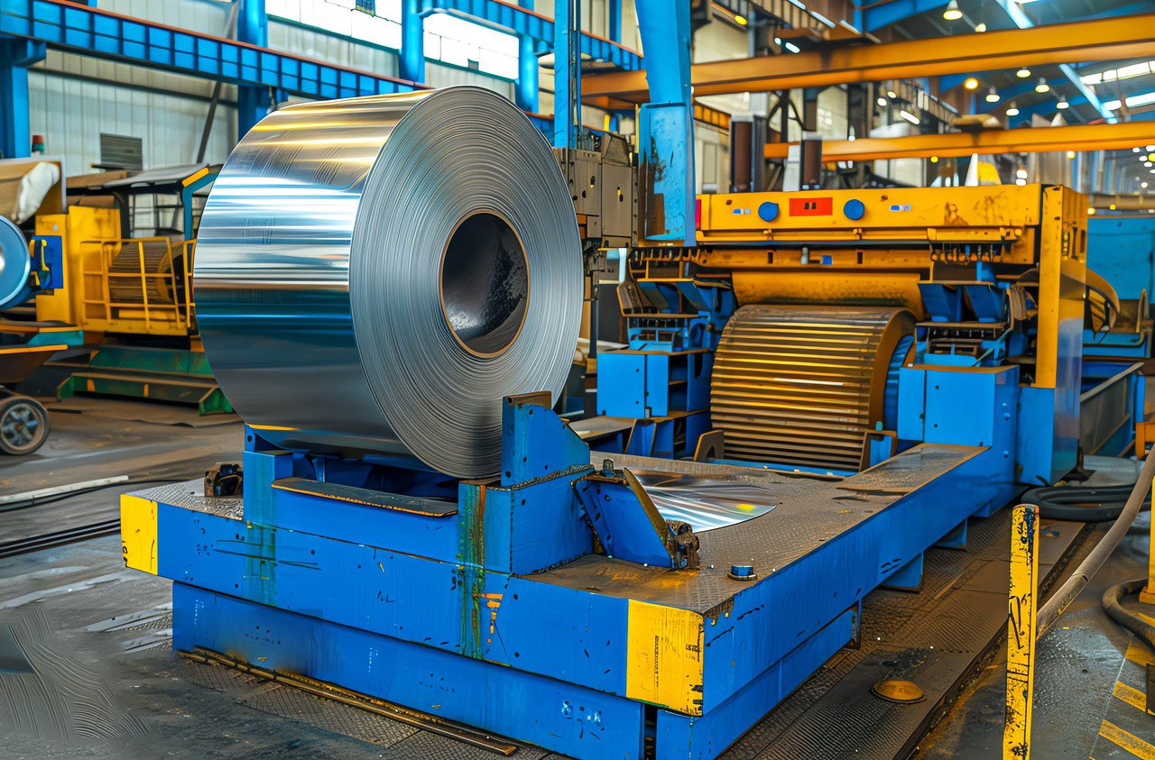
Choosing the correct sheet thickness is a critical engineering decision that sits at the intersection of design intent4, manufacturing capability, and economic reality. It’s not merely a number on a spec sheet; it is a defining characteristic of the final product that dictates its performance, weight, cost, and appearance. An over-specified thickness is a hidden tax on every part you produce, while an under-specified thickness can lead to catastrophic failure. Guiding our clients through this selection process is one of the most important services we provide at MFY. We encourage a holistic analysis that considers the physics of the application and the physics of the cutting process itself.
Matching Thickness to Mechanical Requirements
The primary driver for thickness selection should always be the end-use application. What forces will the part need to withstand? Is it a purely decorative panel, where a thin gauge (e.g., 1.2mm / 18 gauge) is sufficient? Or is it a structural base plate for heavy machinery, requiring a thick plate5 (e.g., 12mm / ~1/2 inch) to prevent bending and vibration? Engineers use tools like Finite Element Analysis (FEA) to simulate stresses and determine the minimum thickness required to meet safety and performance standards.
However, it's also important to consider factors beyond simple strength. Rigidity is key. A large, flat panel made from a thin sheet might be strong enough, but it could feel flimsy or "oil can" (flex and pop). In this case, a slightly thicker sheet might be chosen for improved perceived quality and feel. Conversely, for applications where weight is a penalty, such as in aerospace or automotive parts, the goal is to use the thinnest material possible that still meets all performance criteria. The choice of stainless steel grade also plays a role; some grades are inherently stronger than others, potentially allowing for a reduction in thickness.
The Capabilities and Limits of Your CNC Technology
Once the ideal design thickness is known, you must confront the reality of your manufacturing process. Each CNC cutting method—laser, plasma, and waterjet—has its own strengths and limitations when it comes to thickness.
- Laser Cutting: Fiber lasers excel at cutting thin to medium-thickness stainless steel6 with incredible speed and precision. A 2-4kW laser might efficiently cut up to 8-10mm stainless steel. Higher power lasers (6kW+) can push this to 20mm or more, but cutting speeds drop dramatically, and cut quality can degrade. The heat-affected zone (HAZ), though small, can become more pronounced on thicker sections.
- Plasma Cutting: Plasma is the workhorse for thicker materials. It is significantly faster and cheaper than laser cutting for stainless steel above 12mm. A high-definition plasma system can produce excellent quality cuts on plates up to 25mm (1 inch) or even thicker, though it produces a larger HAZ and a less precise edge than a laser or waterjet.
- Waterjet Cutting: Waterjet is the most versatile technology. Because it's a cold cutting process, there is no HAZ, which is critical for materials whose properties must not be altered by heat. A waterjet can cut virtually any thickness of stainless steel, from 1mm to over 150mm (6 inches). Its primary drawback is its slow cutting speed, which makes it less economical for high-volume production of thinner materials.
A client needing to produce 15mm thick flanges would find laser cutting to be slow and expensive. Plasma would be a faster, more cost-effective choice. If those same flanges required absolutely no heat distortion and a very fine edge finish, waterjet would be the only acceptable method, despite the longer cycle time.
The Economic Impact of Thickness
The financial implications of thickness are twofold. First, there is the direct material cost. Since steel is sold by weight, a 6mm thick sheet costs approximately twice as much as a 3mm thick sheet of the same dimensions. This is a simple but powerful incentive to not over-specify thickness.
Second, there is the processing cost, which is directly tied to CNC machine time. The thicker the material, the slower the cutting speed, and the more time the part spends on the machine. This "machine time" has a high cost associated with it (labor, electricity, consumables, machine amortization). Doubling the thickness can more than double the cutting time. For example, cutting a part from a 10mm sheet on a fiber laser could take three to four times longer than cutting the exact same part profile from a 5mm sheet. Therefore, a small increase in thickness can lead to a large increase in the final part cost. At MFY, we provide a wide spectrum of thicknesses, allowing our clients to choose the precise dimension that optimizes this trade-off between material cost, processing cost, and engineering requirements.
Thicker sheets cut slowerTrue
Increased material thickness requires more power and reduces cutting speed across all CNC methods.
Waterjet creates heat zonesFalse
Waterjet is a cold cutting process that produces no heat-affected zone (HAZ), unlike laser or plasma.
How to ensure precision and quality when working with different sheet sizes in CNC cutting?
Are you struggling to maintain consistent quality across different CNC jobs and sheet sizes? Variations in setup and material can lead to dimensional inaccuracies and poor edge finishes, undermining the precision your customers expect and eroding your reputation for quality.
To ensure precision, consistently use a rigorous setup procedure that includes securing the sheet flat, accurately finding the material's true edge and corner for the program origin, and using the correct cutting parameters (speed, power, gas pressure) validated for that specific thickness.
Quality in CNC cutting is not an accident; it is the direct result of a controlled, repeatable process. Precision is a game of millimeters and microns, and achieving it consistently, regardless of the size of the sheet on the table, requires discipline and attention to detail. The machine can only execute the instructions it's given; the quality of the output is determined by the quality of the inputs—both physical and digital. I often draw on the experience of a client in the medical device industry we supply in the Middle East. For them, precision is non-negotiable. A burr or a slight dimensional error can render a part useless. They have a documented, multi-point checklist that operators must complete for every single job. It covers everything from verifying the material grade and thickness against the work order, to cleaning the support slats, to running a test cut to check for dross. This disciplined approach is why they can hold incredibly tight tolerances7, and it's a model of how to build quality into the process itself, not inspect it in at the end.

Ensuring precision and quality is the final and most critical phase of the CNC cutting process. All the strategic work of selecting the right material size and thickness culminates here, at the cutting head. Achieving excellence requires a holistic approach that integrates machine maintenance, rigorous operational procedures, and a deep understanding of the material's behavior. It’s about creating an environment where sources of error are systematically identified and eliminated. For our partners at MFY, who are leaders in their respective fields, this relentless pursuit of quality is what sets them apart. Our role is to provide them with raw material that is consistent and reliable8, creating the perfect starting point for their own quality assurance systems.
The Foundation: Machine Health and Calibration
You cannot expect a precise part from an imprecise machine. The foundation of quality is a well-maintained and accurately calibrated CNC cutter. This goes beyond routine cleaning. It means regularly checking the machine's geometry: Is the gantry square to the frame? Are the linear guides and ball screws properly lubricated and free of backlash? Any mechanical slop or misalignment in the machine will be directly translated into the cut part.
Calibration is equally vital. For laser cutters, this includes beam alignment and focus calibration to ensure the laser energy is delivered in a tight, consistent spot. For plasma cutters, it means ensuring the torch is perfectly perpendicular to the plate to avoid bevel on the cut edge. Consumables9—nozzles, electrodes, lenses—must be treated as critical components and inspected and replaced regularly. A worn nozzle can cause a distorted cut and excessive dross, instantly compromising quality. A documented, proactive maintenance schedule is not a cost center; it's an investment in precision.
Process Control: Dialing in the Parameters
Once the machine is confirmed to be in optimal condition, the focus shifts to the cutting parameters. This is the set of variables that controls the cutting process itself. For a laser, this includes power (watts), feed rate (mm/min), assist gas type (e.g., Nitrogen, Oxygen), and gas pressure. For plasma, it's amperage, voltage, feed rate, and nozzle standoff height. These parameters are not universal; they must be optimized for the specific grade and thickness of stainless steel being cut.
High-quality fabricators develop and maintain a "cutting library" or parameter charts. When they are cutting 3mm 304 stainless steel, they use a pre-validated set of parameters known to produce a clean, dross-free cut. When they switch to 6mm 316L stainless, they load a different, specific set of parameters. Relying on generic or "close enough" settings is a primary source of quality issues. As mentioned before, a small test cut on a piece of scrap from the actual sheet being used is a best practice to confirm that the parameters are correct before starting the main production run. This allows for small adjustments to account for minor batch-to-batch material variations.
Quality Assurance: In-Process and Post-Process Checks
Quality cannot be delegated solely to a final inspection department. The machine operator is the first and most important line of defense. Operators should be trained to perform in-process checks. After the first part of a nest is cut, they should pause the program and measure its critical dimensions. Does it match the drawing? This simple check can prevent an entire sheet of material from being wasted due to a programming error or incorrect setup.
Operators should also be trained to identify the visual signs of a poor cut. Is there excessive dross (re-solidified metal) on the bottom edge? Is there a noticeable bevel or taper on the cut face? Is the surface finish rough? These are all indicators that a parameter is off or a consumable is worn. Empowering operators to identify these issues and make adjustments is key to maintaining consistent quality. After the parts come off the machine, a final quality control check confirms dimensions, inspects for any defects, and includes processes like deburring to remove any sharp edges, ensuring the part is not only precise but also safe to handle and ready for the next stage of production, like bending or welding.
Machine calibration ensures precisionTrue
Regular calibration of CNC machines, including checking gantry alignment and consumable condition, is essential for maintaining cutting precision.
Generic cutting parameters work for all materialsFalse
Cutting parameters must be optimized for each specific material grade and thickness; using generic settings leads to quality issues.
Conclusion
Selecting the right standard stainless sheet size and thickness is a critical decision for CNC cutting. It requires a balanced analysis of part geometry, production volume, and your machine's capabilities to maximize yield and efficiency. True precision is achieved by combining this strategic choice with rigorous machine preparation and process control.
-
Discover how these tools enhance alignment and accuracy in cutting ↩
-
Understand the advantages of vacuum tables in preventing sheet vibration ↩
-
Explore methods to ensure perfect alignment and cutting precision ↩
-
Learn how sheet thickness impacts design integrity and final product quality ↩
-
Discover how thick plates prevent bending and increase stability in structural uses ↩
-
Understand the speed and precision benefits of laser cutting thin stainless steel ↩
-
Discover how tight tolerances impact quality in precision CNC cutting ↩
-
Learn how consistent materials improve CNC cutting accuracy and reliability ↩
-
Understand the role of consumables in maintaining CNC cutting quality ↩
Have Questions or Need More Information?
Get in touch with us for personalized assistance and expert advice.
![304 Stainless Sheet Price per Ton 2025 [Predictive Insights & Key Factors]](https://mfysteel.com/wp-content/uploads/2025/06/18t07-300x200.png)

