Методы неразрушающего контроля сварных швов нержавеющих труб: Руководство по UT, RT и PT

Are you concerned about the hidden flaws in your stainless steel pipe welds that could lead to catastrophic failures? The immense pressure and corrosive environments these welds endure mean that a single undetected crack can compromise an entire system. Non-destructive testing (NDT) provides the essential assurance you need.
Non-destructive testing (NDT) methods like Ultrasonic Testing (UT), Radiographic Testing (RT), and Penetrant Testing (PT) are crucial for evaluating the integrity of stainless steel pipe welds. They allow inspectors to identify subsurface and surface-level defects without damaging the component, ensuring safety and compliance with industry standards.
Choosing the right NDT method is a critical decision that directly impacts the safety and longevity of your assets. It’s not a one-size-fits-all scenario; the selection depends on the material, application, and potential flaws. In this article, I'll share my experiences at MFY to help you navigate the complexities of UT, RT, and PT, ensuring you make the most informed choice for your projects.
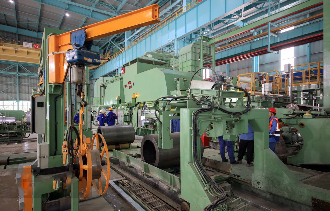
The evolution of NDT is a story of industrial progress. In the early days, the only way to be certain of a weld's strength was to break it. Today, we demand 100% integrity in critical applications like nuclear power plants and offshore oil rigs without destroying a single component. This shift forced the development of sophisticated inspection technologies. At MFY, we’ve seen this firsthand. A client in the chemical processing industry cannot afford any leaks; for them, NDT isn't just a quality check, it's a core part of their risk management strategy. This dialectic between achieving absolute certainty and maintaining operational efficiency is what drives innovation in the field, pushing us towards faster, more accurate, and more reliable methods.
What is the background of NDT methods in stainless pipe welding?
Have you ever wondered how industries guaranteed weld quality before modern technology? Historically, weld inspection often meant destructive testing, a costly and inefficient process that sacrificed the very part it was meant to approve. This created a pressing need for a better, non-invasive solution.
The background of NDT in stainless pipe welding is rooted in the post-WWII industrial boom. The need for rigorous quality control in critical sectors like aerospace and nuclear power drove the evolution from basic visual checks to advanced methods like UT and RT to ensure component safety.
The journey from rudimentary visual inspections to the sophisticated digital methods we use today was not instantaneous. It was propelled by industrial necessity. As projects became more ambitious and the consequences of failure more severe, quality control had to evolve. In my early career, I recall visiting a power generation facility where engineers relied on decades-old radiographic films, a cumbersome but revolutionary process for its time. Today, a similar inspection can be done digitally in a fraction of the time with far greater accuracy. This evolution is particularly relevant for stainless steel, whose unique properties demanded more than just a generic approach. At MFY, we work closely with clients in demanding sectors like LNG and desalination, where the material choice—often a high-grade duplex or austenitic stainless steel—is intrinsically linked to the NDT strategy. Their stringent requirements, governed by standards like ASME B31.3, push us to stay at the forefront of inspection technology, ensuring that the materials we supply can be verified to the highest degree of integrity. This history isn't just academic; it informs the best practices we recommend to clients every day.
The Genesis of Weld Inspection: From Destructive to Non-Destructive
The concept of quality control in welding is as old as the process itself. However, for a significant period, the primary method of verification was destructive. A welder would create a sample coupon alongside the main workpiece, and this coupon would be subjected to bend tests, tensile tests, and acid etching to reveal its internal structure. While effective at validating the welder's procedure and skill, this method had a fundamental flaw: it only certified the sample, not the actual production weld. The assumption was that the production weld would be of identical quality, a risky and often incorrect presumption.
This approach was not only wasteful in terms of materials and labor but also left a cloud of uncertainty over the final product. Imagine constructing a massive pressure vessel or miles of pipeline, only to have confidence in a small, separate piece of metal. This was the reality for engineers for many years. The paradigm shift occurred when industries began to understand risk in a new light. The cost of failure—in terms of financial loss, environmental damage, and human life—far outweighed the cost of developing more advanced inspection techniques. This realization was the true catalyst for the NDT revolution.
The earliest forms of NDT were extensions of human senses. Visual testing (VT), simply looking closely at a weld, is still the most common method. This was followed by Liquid Penetrant Testing (PT) and Magnetic Particle Testing (MT), which enhanced the ability to see tiny surface-breaking flaws. However, the real breakthrough came with methods that could peer inside the weld itself. Radiography (RT) offered a glimpse into the volumetric integrity of the weld, revealing internal porosity and inclusions. Simultaneously, Ultrasonic Testing (UT) was developed, using sound waves to detect and size internal discontinuities, much like sonar. These technologies marked the true beginning of modern, comprehensive weld inspection.
The Influence of Industrial Revolutions on Quality Standards
The adoption of NDT was not uniform; it was driven by the world's most demanding industries. The dawn of the nuclear age in the 1950s and 60s is arguably the single most significant driver for NDT advancement. The catastrophic consequences of a failure in a nuclear reactor component were unthinkable, which led to the establishment of incredibly stringent quality assurance codes, such as the ASME Boiler and Pressure Vessel Code. These codes didn't just recommend NDT; they mandated it, specifying which methods to use, how to perform them, and how to train and certify the technicians.
I worked with a client, an engineering contractor for a petrochemical plant in the Middle East, who lived by these standards every day. Their project involved high-pressure, sour gas pipelines made from our 316L stainless steel pipes. They were required to comply with API 1104, a standard governing the welding of pipelines. Their entire welding and inspection protocol was built around this standard. Every single weld was tracked, inspected using a combination of UT and RT, and documented. For them, NDT was not just a final quality check; it was an integral part of the manufacturing process, with hold points and review stages built around the inspection results.
This formalization spread to other sectors. The aerospace industry, with its focus on lightweight materials and zero-tolerance for failure, heavily advanced UT for inspecting composites and complex alloys. The offshore oil and gas industry, facing immense pressures and corrosive seawater, drove the development of more portable and rugged NDT equipment. The result is the comprehensive ecosystem of codes, standards, and best practices that we have today. These documents represent decades of accumulated knowledge, often learned through hard-won experience, and form the basis of safe engineering practices globally.
Stainless Steel's Unique Role and the NDT Response
Stainless steel, particularly the austenitic grades like 304 and 316, brought its own set of challenges to the NDT world. While prized for its corrosion resistance and durability, its metallurgical structure is very different from that of carbon steel. Austenitic stainless steel has a large, coarse-grained structure. For Radiographic Testing, this isn't a major issue. However, for Ultrasonic Testing, these large grains can scatter and attenuate the sound beam, creating a "noisy" signal that makes it difficult to distinguish between the material's benign structure and a dangerous flaw like a crack.
This "austenitic challenge" required a specialized response. It wasn't enough to simply use the same UT procedures that worked perfectly on carbon steel. The industry had to develop new techniques, such as using lower-frequency transducers to reduce scattering and specialized "angle beam" probes to get sound into the weld in a more effective way. It also placed a much higher premium on technician skill. An inspector needed the experience to differentiate between geometric indications, the inherent noise of the material, and a genuine defect.
This is why, at MFY, when we supply stainless steel pipes for a critical application, our conversation with the client always includes the topic of inspectability. We understand that providing a high-quality product is only half the battle. We must also ensure our client has the knowledge to verify that quality after fabrication. The unique properties of stainless steel make this a collaborative effort between the material supplier, the fabricator, and the NDT provider.
| Характеристика | Destructive Testing (DT) | Non-Destructive Testing (NDT) |
|---|---|---|
| Назначение | Determine mechanical properties (strength, ductility) | Detect flaws and discontinuities (cracks, porosity) |
| Test Subject | A separate sample or the component itself (destroyed) | The actual production component (remains in service) |
| Information | Provides quantitative mechanical data | Provides qualitative and quantitative data on flaws |
| Типичное использование | Procedure qualification, welder qualification, research | In-process and final quality control, in-service inspection |
| Стоимость | Low per test, but high due to destroyed parts | High per test, but low overall as parts are not destroyed |
| Coverage | 0% of production components | Can be up to 100% of production components |
NDT preserves componentsПравда
Non-destructive testing methods allow inspection without damaging the component, unlike destructive testing which requires sacrificing samples.
Visual testing is obsoleteЛожь
Visual Testing (VT) remains the most common NDT method today, despite the development of more advanced techniques.
How are UT, RT, and PT methods currently used for stainless pipe welds?
Faced with multiple NDT options, how do you select the right one for your specific needs? Choosing incorrectly can mean either missing a critical flaw or spending excessively on unnecessary inspections. The key is to understand the distinct application of each primary method.
Currently, Penetrant Testing (PT) is used for detecting surface-breaking flaws, Radiographic Testing (RT) is used for identifying volumetric internal defects like porosity, and Ultrasonic Testing (UT), especially advanced methods like PAUT, is used for detecting and sizing critical planar flaws like cracks and lack of fusion.
These three methods—UT, RT, and PT—form the backbone of modern weld inspection, but they are not interchangeable. Each has its strengths and weaknesses, and the optimal choice is a strategic decision dictated by technical requirements, accessibility, and cost. Think of it as a doctor choosing between an X-ray, an MRI, or a surface examination; each reveals different things. I recently guided a client in Southeast Asia who was constructing a large-scale LNG processing facility. The project involved miles of austenitic stainless steel piping, and they were debating between 100% radiography and a more modern approach using phased array ultrasonic testing (PAUT). We walked through the pros and cons, considering the specific weld types and the critical nature of finding planar defects. By analyzing their specific needs, we helped them develop an inspection protocol that utilized PAUT for critical butt welds and PT for socket welds, optimizing both safety and project efficiency. This experience highlights a core belief we hold at MFY: a successful project depends not only on the quality of the steel but also on the intelligence of its verification process.
Ultrasonic Testing (UT): Precision in Volumetric Inspection
Ultrasonic Testing is the workhorse for detecting and, crucially, sizing internal flaws, especially planar defects which are often the most dangerous. In its conventional form, a single transducer sends a sound beam into the material at a specific angle. Today, the industry is rapidly moving towards more advanced UT methods, namely Phased Array Ultrasonic Testing (PAUT)1 and Time-of-Flight Diffraction (TOFD). PAUT utilizes a probe with multiple small elements that can be pulsed individually. By controlling the timing of these pulses, the system can "steer" the sound beam across a range of angles and focus it at specific depths, all without moving the probe. This creates a detailed cross-sectional image of the weld, almost like a medical ultrasound, making flaw detection and interpretation far more intuitive and reliable.
TOFD, often used in conjunction with PAUT, is another powerful technique. It uses two probes, a transmitter and a receiver, placed on either side of the weld. It measures the time it takes for the sound waves to diffract from the very top and bottom tips of a flaw. This allows for incredibly accurate through-wall sizing of defects, which is critical for fracture mechanics analysis and "fitness-for-service" assessments. For a client of ours in India manufacturing high-pressure vessels with our 316L stainless pipes, we recommended a PAUT/TOFD approach. They were concerned about potential lack of root fusion, a difficult flaw to detect with radiography. The PAUT scans provided clear images of the root area, and TOFD gave them precise height measurements of any indications, giving them the high degree of confidence required by their international customer. Studies have shown that for certain critical flaws, PAUT can improve the probability of detection by over 20% compared to conventional single-probe UT.
The implementation of these advanced UT methods requires significant investment in equipment and, most importantly, in operator training. An inspector running a PAUT system is interpreting complex data and needs a deep understanding of the technique and the material. However, the benefits in terms of speed, data recording, and detection capability are undeniable. For automated welding processes, where weld quality is generally high but must be verified, a rapid PAUT/TOFD scan is vastly more efficient than traditional radiography, which involves chemical processing and radiation safety zones.
Radiographic Testing (RT): A Window into the Weld's Core
Radiographic Testing has been a cornerstone of weld inspection for decades. By passing X-rays or gamma rays through the weld onto a detector (either film or a digital sensor), RT creates a 2D shadow image of the weld's internal structure. Denser areas absorb more radiation and appear lighter, while less dense areas (like a gas pore or slag inclusion) allow more radiation to pass through and appear darker. This makes RT exceptionally good at detecting volumetric flaws. Its results are also pictorial, creating a permanent record that is relatively easy for different parties to interpret.
The biggest evolution in this space has been the transition from film to digital radiography (DR). Instead of waiting for film to be developed in a darkroom, DR systems provide an image on a computer screen within seconds. This dramatically speeds up the inspection cycle. Furthermore, digital images can be enhanced, magnified, and analyzed with software tools to improve interpretation. A construction contractor in the Middle East, building a desalination plant with our duplex stainless steel pipes, made the switch from film to DR mid-project. They reported a 40% reduction in inspection time per weld, which, across thousands of welds, translated into significant cost savings and allowed them to stay ahead of a tight construction schedule.
However, RT has limitations. It is less sensitive to planar defects like cracks or lack of fusion, especially if the flaw is not favorably oriented to the radiation beam. A tight crack perpendicular to the beam may be completely invisible on the radiograph. It also involves significant safety protocols due to the use of ionizing radiation, requiring the evacuation of non-essential personnel and the establishment of controlled areas. This can be disruptive on a busy construction site. Therefore, the choice between RT and UT is often a choice between better detection of volumetric flaws (RT) versus better detection of planar flaws (UT).
Penetrant Testing (PT): Uncovering Surface-Level Threats
Penetrant Testing is one of the oldest and most straightforward NDT methods, yet it remains indispensable for finding flaws that break the material's surface. It cannot detect anything purely subsurface. The process is simple and effective: first, the surface is thoroughly cleaned. Second, a brightly colored or fluorescent liquid dye (the penetrant) is applied. The penetrant is drawn into any surface-breaking cracks, pores, or seams by capillary action. After a specific "dwell time," the excess penetrant is carefully removed from the surface.
ly, a developer (typically a fine white powder) is applied. The developer acts like a blotter, drawing the trapped penetrant back out of the flaw. The penetrant then spreads out against the white background, creating a visible indication that is much larger than the flaw itself, making it easy to see. For an even higher level of sensitivity, fluorescent penetrants are used, which are viewed under a black light, causing the indications to glow brightly.
We have a long-standing client who distributes our stainless steel pipes to the food and beverage industry. For them, PT is a routine quality assurance check. In food processing, any surface crack, no matter how small, can harbor bacteria and compromise hygiene. They use PT on welds and fittings to ensure a perfectly smooth and crevice-free surface. It's a cost-effective, portable, and versatile method that requires minimal equipment. While it's limited to surface defects, for many applications, that is the primary area of concern, making PT an essential tool in the NDT toolkit.
| Метод | Primary Target Flaws | Key Advantages | Key Limitations |
|---|---|---|---|
| Ультразвуковой контроль (UT) | Planar defects (cracks, lack of fusion), subsurface flaws | High sensitivity to critical flaws, accurate sizing, fast, portable | Operator skill dependent, issues with coarse-grain materials |
| Radiographic Testing (RT) | Volumetric defects (porosity, slag), subsurface flaws | Provides a permanent image record, good for volumetric flaws | Radiation hazard, less sensitive to planar flaws, time-consuming (film) |
| Penetrant Testing (PT) | Surface-breaking defects (cracks, porosity, seams) | Low cost, portable, easy to use, highly sensitive to fine cracks | Only detects surface-breaking flaws, surface prep is critical |
PT detects surface flawsПравда
Penetrant Testing is specifically designed to identify surface-breaking defects through capillary action of colored dyes.
RT detects all flaw types equallyЛожь
Radiographic Testing excels at volumetric defects but has poor sensitivity to planar flaws oriented perpendicular to the radiation beam.
What challenges are faced while using NDT methods for stainless pipe welds?
As powerful as NDT methods are, they are not magic wands. Assuming they are foolproof can lead to a false sense of security. Misapplication or misinterpretation of results can have consequences just as severe as not inspecting at all, leading to unnecessary repairs or worse, in-service failures.
Key challenges in NDT for stainless pipe welds include ultrasonic signal loss and noise from the coarse austenitic grain structure, the insensitivity of radiography to misaligned planar flaws, the limitation of penetrant testing to only surface defects, and the high dependency on technician skill and experience.
Overlooking these challenges transforms a quality assurance tool into a potential liability. It's not just about the technical limitations; it's about business risk. A "false positive," where a benign indication is misidentified as a critical flaw, leads to costly and schedule-delaying repairs that were never needed. A "false negative," where a genuine defect is missed, can have catastrophic safety and financial implications down the line. I remember a case with a client where a series of UT inspections on a critical pipeline produced ambiguous and non-repeatable results. Panic began to set in until we brought in a Level III NDT specialist. He traced the issue not to the welds themselves, but to an incorrect probe frequency and wedge selection for the specific grade of duplex stainless steel being used. The equipment was not properly calibrated for the material's acoustic properties. This experience was a stark reminder that the effectiveness of NDT is a chain only as strong as its weakest link: the equipment, the procedure, and the operator. At MFY, this is why we stress the importance of a holistic approach to quality.
The Austenitic Challenge: Ultrasonic Wave Attenuation and Scattering
The single greatest material-specific challenge in the NDT of stainless steel pipes is the nature of austenitic welds. When carbon steel cools, its grain structure refines into small, uniform, equiaxed crystals. This creates a relatively clear path for an ultrasonic sound wave to travel through. Austenitic stainless steel, however, behaves differently. During solidification, the weld metal forms large, elongated, columnar grains that are anisotropic, meaning their acoustic properties differ depending on the direction of the sound wave.
When a UT beam enters this structure, two things happen: attenuation and scattering. Attenuation is the loss of sound energy as it's absorbed by the material, weakening the signal. Scattering occurs when the sound beam hits the boundaries of these large grains and is deflected in multiple directions, much like light hitting a prism. This scattered energy returns to the transducer as "hash" or "grass" on the screen—a high level of background noise. A real flaw, like a crack, might be hidden within this noise, making it incredibly difficult to detect. The signal-to-noise ratio, a key metric for inspection reliability, can be drastically lower in austenitic welds compared to their carbon steel counterparts.
This challenge makes conventional UT highly unreliable on austenitic stainless welds, especially thicker sections. It demands a more sophisticated approach. Inspectors must use specialized techniques, such as employing lower frequency transducers (which scatter less but offer lower resolution) and dual-element probes that focus sound just below the surface. More advanced solutions like Phased Array UT are often required to overcome the noise, but even these require procedures specifically developed and validated for austenitic materials.
Radiography's Blind Spots and Interpretation Ambiguity
While radiography sidesteps the ultrasonic issues of grain structure, it has its own significant limitations, chief among them being its weakness in detecting planar flaws. A radiograph is a 2D shadow picture. For a flaw to be visible, it must have a measurable thickness in the direction of the radiation beam. Volumetric flaws like a round gas pore or an irregular slag inclusion show up well. However, a fine crack or a thin line of lack of fusion is a planar flaw—it has length and height, but virtually no thickness.
If the radiation beam happens to pass directly along the height of the crack, it may show up as a faint line. But if the beam is even slightly angled to the plane of the crack, its "shadow" becomes so thin that it is completely invisible on the radiograph. Given that weld cracks can occur in any orientation, there is a significant risk that RT will miss the most dangerous types of flaws. This is a well-documented limitation, and it's why many critical service standards now mandate UT in addition to or instead of RT.
Furthermore, the interpretation of radiographic film has a degree of subjectivity. Distinguishing between a slag line and a crack, or assessing the density of scattered porosity, requires a trained and experienced eye. I once mediated a dispute between a fabricator and their end-user in Russia over an RT film. The client's inspector interpreted a faint line as a crack, demanding a costly repair, while the fabricator's team saw it as a benign surface indication. The ambiguity was only resolved by performing a follow-up UT inspection, which confirmed it was not a crack. This highlights how reliance on RT alone can lead to conflict and unnecessary work, a problem that digital radiography with its enhancement tools can help mitigate, but not eliminate entirely.
The Human Factor: Skill, Training, and Certification
Ultimately, the most sophisticated NDT equipment in the world is useless in the hands of an untrained or unmotivated operator. NDT is often described as a blend of science and art, and this is especially true for ultrasonic and radiographic testing. The inspector is not just running a machine; they are actively interpreting data, making judgments, and applying standards. The reliability of an inspection is directly proportional to the competence of the person performing it.
This "human factor" is a major challenge. A properly certified inspector (e.g., to ASNT SNT-TC-1A or ISO 9712 standards) has demonstrated a baseline level of knowledge and skill. However, certification alone is not enough. Experience with the specific equipment, procedure, and material being tested is paramount. An inspector who has spent years looking at carbon steel welds may struggle to interpret the noisy signals from an austenitic stainless steel weld. A rushed inspection, poor surface preparation, or improperly calibrated equipment can invalidate the entire test.
We once had to assist a client who was experiencing a high rate of weld rejections from their NDT subcontractor. After a review, we found the issue wasn't the welding but the NDT procedure. The subcontractor was using a generic protocol and their technicians, while certified, had little experience with the duplex stainless steel pipes MFY had supplied. By helping our client develop a more detailed procedure and bringing in a consultant to provide specific training, the rejection rate dropped to almost zero. This demonstrates that investing in qualified and properly trained personnel is not an overhead cost; it is a fundamental requirement for effective quality assurance.
| Вызов | Primary Method Affected | Impact on Reliability |
|---|---|---|
| Coarse Grain Structure | Ультразвуковой контроль (UT) | High signal noise, loss of signal, can mask real flaws. |
| Planar Flaw Orientation | Radiographic Testing (RT) | High probability of missing critical flaws (cracks, lack of fusion). |
| Surface-Only Detection | Penetrant Testing (PT) | Cannot detect any subsurface or internal flaws. |
| Technician Skill/Experience | All Methods (especially UT) | High potential for misinterpretation, false positives, or false negatives. |
| Weld Geometry/Access | UT and RT | Complex shapes or limited access can make a complete inspection impossible. |
UT struggles with austenitic grain noiseПравда
Austenitic stainless steel's coarse grain structure causes ultrasonic scattering and attenuation, creating background noise that can mask real flaws.
RT detects all crack orientations equallyЛожь
Radiography often misses planar flaws unless the radiation beam aligns perfectly with the flaw plane - most cracks have orientation-dependent detectability.
What solutions can address the challenges in NDT methods for pipe welds?
Knowing the challenges is only half the battle; the real value lies in deploying effective solutions. The daunting prospect of missed flaws and noisy data in stainless steel inspection can be overcome. Modern technology and rigorous processes provide a clear path to reliable results.
Key solutions include implementing advanced Ultrasonic Testing methods, like Phased Array (PAUT) and Time-of-Flight Diffraction (TOFD), to overcome grain structure issues. Adopting Digital Radiography (DR) enhances analysis and speeds up workflow. Most importantly, enforcing rigorous, specific NDT procedures and demanding stringent personnel certification and training ensures reliable and repeatable results.
Moving from being problem-aware to being solution-oriented is the most critical step in ensuring weld integrity. It's about transforming technical challenges into opportunities for greater control and confidence. At MFY, we see this as a core part of our responsibility. Our role doesn't end when the stainless steel pipe is delivered to the site; we see ourselves as partners in our clients' success. We actively guide them through the complexities of post-fabrication quality assurance. I often tell my team that a client who knows how to properly inspect our product is our best customer, because they will be able to prove the quality we deliver. This solution-focused mindset is about leveraging the right technology and methodology to turn uncertainty into certainty. It’s about building a framework for success that combines advanced tools with human expertise, ensuring that every weld is safe, sound, and fit for service. This proactive approach prevents problems before they arise, saving our clients time, money, and protecting their reputation.
Advanced Ultrasonics: Overcoming Austenitic Grain Structures
The most direct solution to the "austenitic challenge" in UT is to fight technology with technology. Advanced ultrasonic systems, particularly Phased Array UT (PAUT)2, are purpose-built to solve these kinds of problems. Unlike a conventional UT probe that sends a single beam at a fixed angle, a PAUT probe's multiple elements can be electronically controlled to generate a beam that sweeps through a whole range of angles (a "sector scan"). This multi-angle approach dramatically increases the chances of the sound beam hitting a flaw at a perpendicular angle, maximizing the reflection and making it visible.
Furthermore, PAUT systems allow for precise focusing of the sound beam. This concentrates the acoustic energy in a specific area, which helps to "punch" the signal through the coarse-grained, attenuative material and improves the signal-to-noise ratio. The system’s software can then compile all this information into a single, easy-to-interpret image of the weld's cross-section. Recent studies and industry data confirm the effectiveness of this approach, with some reports showing that the probability of detection (POD) for critical flaws in austenitic welds can be increased by as much as 30% with PAUT compared to conventional UT. This isn't just an incremental improvement; it's a step-change in reliability.
In addition to PAUT, the use of specialized probes is a key part of the solution. Low-frequency transducers (e.g., 1.5-2.5 MHz instead of the more common 5 MHz) are less susceptible to scattering from grain boundaries. Dual-element "pitch-catch" probes, where one element transmits and a separate one receives, can be optimized to inspect the noisy weld root and crown areas. Combining these advanced hardware solutions with sophisticated signal processing algorithms creates a powerful toolkit for reliably inspecting even the most challenging stainless steel welds.
The Digital Revolution in Radiography
For radiography, the most impactful solution has been the transition from analog film to digital platforms. This includes Computed Radiography (CR) and Direct Radiography (DR)3, which uses a flat-panel detector to create an image instantly. The benefits are transformative for workflow and analysis. The elimination of chemical processing alone saves immense amounts of time, labor, and environmental waste. An inspection team can see the results of a shot within seconds, confirm they have a good image, and move to the next weld, dramatically increasing productivity.
I recall a large-scale power plant construction project we supplied in Southeast Asia where the contractor was struggling with inspection bottlenecks. They were radiographing hundreds of critical welds using traditional film. By switching to a DR system, they cut their inspection and reporting time for each weld from over an hour to less than 15 minutes. This allowed them to clear backlogs and keep pace with the welders. The project's quality manager told me the biggest advantage wasn't just speed, but data integrity. Digital images can't be lost or degraded like film, and they are easily stored and shared electronically, creating a robust audit trail.
Beyond workflow, digital radiography offers powerful analytical tools. The software allows an inspector to change the brightness and contrast, zoom in on specific areas, and apply filters to enhance the visibility of subtle indications. This reduces the subjectivity of interpretation and can make the difference in correctly identifying a faint flaw. While digital RT doesn't solve the inherent limitation of detecting misaligned planar flaws, it makes the data that is captured far more useful, shareable, and reliable.
Standardizing Excellence: The Role of Procedures and Qualifications
Technology alone is not a complete solution. The single most important factor in ensuring NDT effectiveness is a robust framework of human and procedural controls. This begins with a written NDT procedure that is specific to the job. A generic, one-page procedure is not acceptable for critical work. A proper procedure, in line with codes like ASME Section V, should be a detailed recipe for the inspection. It must specify the exact NDT method(s) to be used, the make and model of the equipment, the specific probes and wedges, the calibration standards, the scanning patterns, the data recording settings, and the precise acceptance criteria that define what constitutes a rejectable flaw.
This procedure must be qualified. This is often done by demonstrating its effectiveness on a mock-up block of the same material and thickness, containing manufactured flaws of known size and type. If the procedure can't find the known flaws in the test block, it certainly can't be trusted on a production weld. This verification step is absolutely critical and provides objective evidence that the chosen technique actually works.
Complementing the procedure is personnel qualification. It is essential to ensure that the technicians performing the work are certified to the appropriate level (e.g., Level II for performing tests, Level III for developing procedures and providing oversight) in the specific NDT method they are using. But for challenging materials like stainless steel, simple certification is not enough. Clients should require and verify that the NDT personnel have specific, documented experience in testing austenitic or duplex materials. This combination of a validated procedure and a proven technician creates a system of excellence that minimizes ambiguity and maximizes reliability.
| Problem | Technological Solution | Procedural Solution |
|---|---|---|
| UT Noise in Austenitic Welds | Phased Array UT (PAUT), TOFD, Low-Frequency Probes | Require procedure validation on material-specific mock-ups. |
| RT Insensitivity to Cracks | Use UT (especially PAUT/TOFD) as the primary method for critical welds. | Write procedures that mandate UT for planar flaw detection. |
| Subjective Interpretation | Digital Radiography (DR) with analysis tools, PAUT imaging | Require Level II/III certified personnel with documented experience. |
| Inconsistent Results | Standardized digital equipment (PAUT, DR) | Develop and enforce detailed, job-specific NDT procedures. |
| Отсутствие прослеживаемости | Digital data acquisition and storage for all inspections | Implement a robust quality management system for NDT records. |
PAUT improves flaw detectionПравда
Phased Array UT's multi-angle scanning increases probability of detecting flaws in austenitic welds by up to 30% compared to conventional UT.
Digital RT uses film processingЛожь
Digital Radiography eliminates chemical film processing, using instant digital detectors instead, which improves workflow efficiency.
What technical recommendations can enhance NDT effectiveness for pipe weld inspections?
You have the right tools and a solid procedural framework, but how do you elevate your inspection from merely compliant to truly effective? The final layer of success lies in a set of technical best practices. Applying these recommendations ensures you are maximizing the potential of your NDT program.
Key technical recommendations include designing welds for inspectability from the start, mandating advanced methods like Phased Array Ultrasonic Testing (PAUT) for critical austenitic welds, and always validating procedures on realistic mock-ups. Furthermore, integrating digital NDT data into a larger quality management system creates a powerful feedback loop for continuous improvement.
These recommendations represent a shift from a reactive to a proactive quality mindset. Instead of simply finding flaws after they are created, this approach aims to build a system where quality is verifiable at every stage. At MFY, our vision extends beyond being a leading supplier of stainless steel; we aim to be a partner in building robust and reliable infrastructure. This means sharing the knowledge and best practices that we have accumulated from working on projects across the globe. When we provide technical recommendations to a client—whether it's for an equipment integrator in Russia or a construction contractor in India—we are helping them build a competitive edge through superior quality assurance. It's about instilling a culture where inspection is not seen as an expense to be minimized, but as an investment in long-term safety, reliability, and reputation.
The "Design for Inspectability" Philosophy
The most effective and often least costly way to enhance NDT is to plan for it before a single arc is struck. "Design for Inspectability" (DFI) is a philosophy that integrates the requirements of future inspections into the design phase of a component or system. All too often, engineers design a weld joint purely for structural strength or ease of welding, only for the NDT team to later discover that they cannot physically get a probe onto the surface or that the joint geometry creates insurmountable inspection challenges.
For example, a sharp, narrow V-groove weld prep might be easy to weld, but it creates geometric reflectors in the root that can be easily confused with cracks during a UT scan. A wider U-groove or a compound bevel might provide a much "cleaner" ultrasonic inspection. Similarly, placing a weld too close to a flange, elbow, or support bracket can make it impossible to position an RT film or a UT scanner. By having an NDT professional (ideally a Level III) review the designs early on, these issues can be easily rectified on paper, saving enormous costs and headaches that would otherwise arise from trying to inspect an "un-inspectable" weld.
Surface condition is another critical aspect of DFI. NDT methods require a smooth, clean surface for accurate results. A UT transducer needs good contact to transmit sound, and PT requires a surface free of grease and scale. Specifying that the weld cap be ground smooth and flush, rather than left in its rough, "as-welded" condition, can dramatically improve the quality of an inspection. This simple foresight, this collaboration between designers and inspectors, is a hallmark of a mature quality organization. It treats inspection not as an afterthought, but as a critical design requirement.
Validation and Verification: The Power of Mock-ups
A written procedure is a recipe, but how do you know the recipe works for your specific kitchen? The answer is through rigorous validation using realistic mock-ups. A mock-up is a practice piece—a section of pipe of the same material, diameter, thickness, and weld preparation as the production welds—into which known flaws have been intentionally placed using methods like Electrical Discharge Machining (EDM)4 or by introducing actual welding defects. This "flawed but known" sample is the ultimate test for your NDT system.
Before starting production work, the NDT team must demonstrate that their proposed procedure (equipment, personnel, and technique) can successfully detect and correctly characterize the flaws in the mock-up. If the procedure calls for detecting 1mm-high cracks, the mock-up should contain 1mm-high notches. If the NDT system cannot reliably find these known defects, it has failed validation and cannot be used. This process, often referred to as a Probability of Detection (POD) study or a technical justification, removes all doubt and provides objective, documented evidence of the procedure's capability.
This practice is mandated by many high-level codes, such as ASME Section V and European standards, for a reason. It is the single best way to ensure that your NDT program is not just going through the motions but is genuinely effective. For a major project, we once supplied duplex stainless steel pipes and insisted the client invest in creating a comprehensive set of calibration blocks and a full-scale weld mock-up. Initially, they were hesitant about the upfront cost. However, during validation, the mock-up revealed that their initial UT procedure was missing a specific type of sidewall flaw. By discovering this in the lab, they were able to adjust their technique before inspecting hundreds of production welds, preventing a potential systemic quality issue.
Data-Driven Quality Control: Integrating NDT into the Digital Workflow
The final recommendation is to treat NDT data not as a series of isolated pass/fail reports, but as a rich stream of information that can be used for process control. Modern digital NDT methods like PAUT and Digital Radiography (DR) generate vast amounts of data. A single PAUT scan of a weld contains thousands of individual data points. This data should be digitally archived, not just stored in a folder, but integrated into a larger quality management or asset integrity database.
By doing this, you can move beyond looking at individual welds and start analyzing trends. Is a particular welder consistently producing welds with minor porosity? Is a specific welding machine drifting out of its parameters, leading to a subtle change in the weld profile that NDT is picking up? By trending NDT data over time and correlating it with welding parameters, you can identify systemic issues and implement corrective actions. This creates a powerful feedback loop for continuous improvement, shifting the focus from simply finding defects to preventing them from occurring in the first place.
This data-driven approach is at the heart of Industry 4.05 and aligns perfectly with MFY's commitment to digital innovation. When NDT data is integrated, it becomes part of the asset's "digital twin." For the entire life of that pipe, from construction to operation to eventual decommissioning, a complete record of its internal condition exists. This information is invaluable for making informed decisions about maintenance, repairs, and fitness-for-service assessments, ultimately leading to safer, more reliable, and more efficient operations.
| Recommendation | Actionable Step | Выгода |
|---|---|---|
| Design for Inspectability | Involve NDT Level III personnel in the design review phase. | Prevents costly rework, ensures 100% inspection coverage is possible. |
| Mandate Advanced Methods | Specify PAUT/TOFD in technical specifications for critical austenitic/duplex welds. | Significantly increases the probability of detecting critical planar flaws. |
| Validate with Mock-ups | Fabricate mock-ups with realistic, known flaws for procedure qualification. | Provides objective evidence that the NDT procedure is effective and reliable. |
| Specify Surface Finish | Require weld caps to be ground smooth in welding procedures. | Improves data quality for UT and reduces false calls for PT. |
| Integrate Digital Data | Archive digital NDT data (PAUT, DR) in a central database. | Enables trend analysis, process control, and lifetime asset management. |
Design for inspectability prevents costly reworkПравда
Involving NDT professionals early in design avoids geometric issues that make welds un-inspectable later.
Mock-ups are optional for NDT validationЛожь
ASME Section V and European standards often mandate mock-ups with known flaws for procedure validation.
Заключение
Ultimately, selecting the right NDT method—UT, RT, or PT—is a strategic technical decision. Applying these methods with rigor, through advanced techniques, validated procedures, and skilled personnel, is not just a quality check, but a foundational pillar for ensuring the long-term safety and reliability of your stainless steel assets.
-
Explore why PAUT enhances accuracy and detection in weld inspections ↩
-
Explore how PAUT improves flaw detection reliability in austenitic welds ↩
-
Learn about the benefits of using DR technology in NDT processes ↩
-
Understand EDM's role in preparing test samples for NDT ↩
-
Discover Industry 4.0's impact on digital data integration in NDT ↩
У вас есть вопросы или нужна дополнительная информация?
Свяжитесь с нами, чтобы получить индивидуальную помощь и квалифицированный совет.